16+ Engineering Process Flow Diagram Symbols Background. The pfd displays the relationship between major equipment of a plant facility and does not show minor details such as piping details. A process flow diagram (pfd) is a diagram commonly used in chemical and process engineering to indicate the general flow of plant processes and equipment.
Flowchart in Software Engineering / Testing from mundrisoft.com They will help you draw any chemical or process flow diagram in mere minutes. It is a type of data or information that can be read by people, such as a printed report, for example. Process flow diagram (pfd) is a simple drawing that shows the relationships between major equipment in a process plant using equipment symbols and a technician or engineer can use this document to trace the flow of materials through the unit.
The flow diagram is also used for visitor.
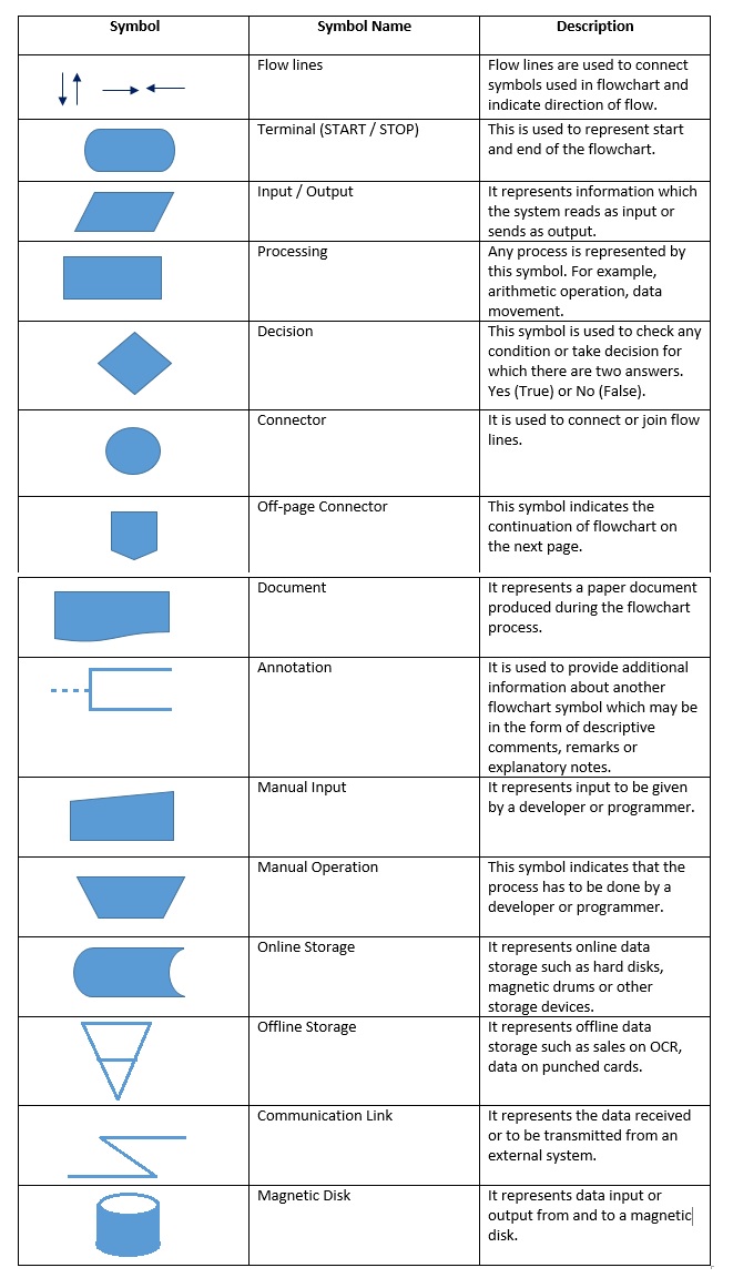
Review symbols and learn about best practices. Here, we've got the four flowchart symbols you've got to know, plus a rundown on some more intermediate process symbols if you're looking for extra credit. Frank gilberth introduced flowcharts in 1921, and they were called process flow charts at the beginning. Yourdon and coad and gane and sarson.
Share this post
0 Response to "Engineering Process Flow Diagram Symbols"

0 Response to "Engineering Process Flow Diagram Symbols"
Post a Comment